Getting Started
The Flashkeeper project develops several different hardware devices for interfacing with, managing, and protecting different SPI flash devices. This page lists multiple Flashkeeper use cases, and suggests a set of devices which might be useful for each.
Table of Contents
- Getting Started
- I’m a user who wants to protect my firmware against tampering
- I’m a user who wants an easier way to reprogram the flash chip in my system
- I’m a firmware developer who wants to test my firmware builds more efficiently
- I want to experiment with various flash chip packages, or to adapt a modern flash chip to an old motherboard
I’m a user who wants to protect my firmware against tampering
You can use a Flashkeeper WP-only chip adapter to write-protect your flash chip. On most modern SPI flash devices, this will allow you to use partial write-protection support in Flashrom, for example to protect the Coreboot bootblock while permitting modification elsewhere. Since nearly all PC motherboards use “wide” flash chips, you will probably need the wide chip adapter variant. Currently, only the soldered chip adapter variants have been validated.

If your chassis provides enough space above your flash chip, consider adding the CVS-01TB DIP switch, so that you can enable and disable write-protection by hand. If it doesn’t (such as in some thin laptops), or if you don’t want to add the switch, you can instead bridge and unbridge the built-in solder jumper to enable and disable write-protection.
You’ll need:
- The WP-only chip adapter for your flash chip (almost certainly
adapter_soldered/wp_only_wide) - A Nidec CVS-01TB SMT DIP switch (if you have a “bare board” flash adapter and wish to add a mechanical WP switch to it)
I’m a user who wants an easier way to reprogram the flash chip in my system
The breakout chip adapter allows you to extend your SPI bus off of the flash chip and over a standard 8-pin flex cable to a removable “dummy board”, providing a more convenient place to connect a programmer in many chassis.
First, select a location in your chassis to run the breakout cable out of. The cable is 4.5mm wide, approximately 0.1mm thick, and can be folded and curved as necessary to reach your desired location. In desktops, the cable can often be run out the front panel or into the bottom of the case. In laptops, consider putting the end of the cable under a removable panel (such as a memory or battery hatch) so that it can be covered when not in use, or running it out between the chassis and the housing of a port (such as “on top of” a USB-A connector).
For best signal integrity (SPI buses usually operate at reasonably high frequencies), choose the shortest available cable that will reach your desired location.
You’ll need:
- The breakout chip adapter (
adapter_soldered/breakout_wide) - A standard “reverse-order”/”B-type”, 8-pin, 0.5mm pitch flat-flex cable, in the length you need. AliExpress and Amazon
- The dummy board (
dummy_board), to connect your external programmer to the FFC - An SPI flash programmer of your choice
I’m a firmware developer who wants to test my firmware builds more efficiently
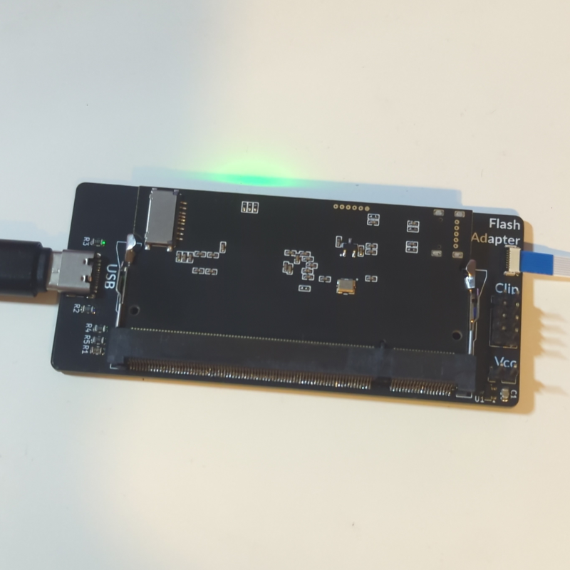
The SPI Emulator and Probe (aka “SPIspy board”) is a development tool which allows you to emulate an SPI flash chip using SPIspy. The flash image is held in RAM on the FPGA, allowing it to be reprogrammed over USB far more rapidly than programming a conventional SPI flash chip. It’s designed to connect to a breakout chip adapter over the same FFC it usually uses, or to a standard Pomona clip (via a standard 2.54mm-pitch jumper wire header).
For more information on SPIspy with Flashkeeper, see the spispy_flashkeeper repository.
You’ll need:
- The SPI Emulator and Probe (
spispy_board) - An interface to your flash chip, either:
- The breakout chip adapter (
adapter_soldered/breakout_wide) - A standard “reverse-order”/”B-type”, 8-pin, 0.5mm pitch flat-flex cable, in the length you need. AliExpress and Amazon
- The breakout chip adapter (
- or,
- A standard Pomona-style “chip clip”
- Appropriate 2.54mm-pitch cabling to connect it to a 2.54mm-pitch pin header
I want to experiment with various flash chip packages, or to adapt a modern flash chip to an old motherboard
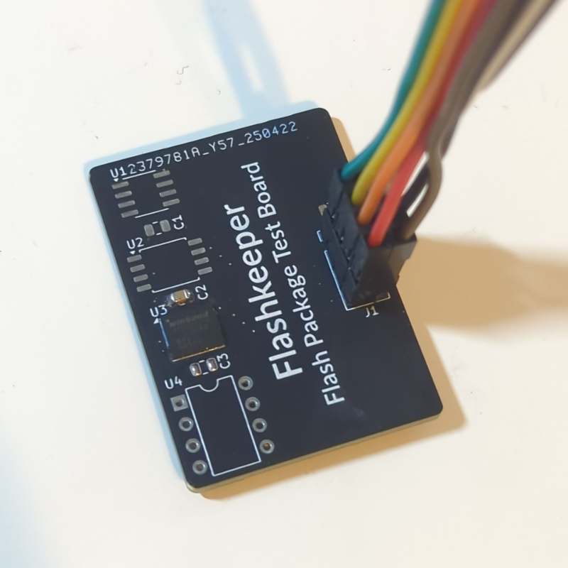
The Flash Package Test Board (aka “dummy board”) was initially developed for testing other Flashkeeper hardware, but has turned out to be quite a useful adapter in its own right. It’s simple PCB, with flash package footprints for narrow and wide SOIC-8, 5x6mm WSON-8, and DIP-8, as well as a standard 2.54mm pin header and (on newer versions) an 8 pin FFC ZIF socket (to connect to the SPI Emulator and Probe or the Breakout Adapter). By adding two pin headers, it can be used as a SOIC/WSON to DIP-8 adapter (for older motherboards such as the KGPE-D16 which use DIP flash chips).
By soldering a SOIC-8 ZIF socket onto its SOIC-8 Wide footprint, the board can also be used to program loose SOIC flash chips, such as during manufacturing. Either connect it to a programmer via one of its connectors, or attach a pin header to its DIP footprint and place the entire dummy board, socket and all, into the DIP ZIF socket on your programmer.
On DIP motherboards, the dummy board can also be used as either types of chip adapter - to WP your flash chip (like the WP-only chip adapter), connect a jumper between the WP and GND pins of the 2.54mm header. To extend your SPI bus over an FFC (like the breakout chip adapter), use either that header or the FFC ZIF socket with a cable of your choosing.
You’ll need:
- The dummy board (
dummy_board) - (likely) an SPI flash programmer (e.g. CH341a)
- Additional hardware of your choosing, for your application